Electromagnetic induction
A The potential difference (or voltage) of a supply is a measure of the energy given to the charge carriers in a circuit. Units = volts (V). This is the voltage between two points that makes an electric current flow between them. or A measure of the electrical work done moving each unit of charge around a circuit. is needed to make an electric current flow in a circuit. An electric circuit is induced when:
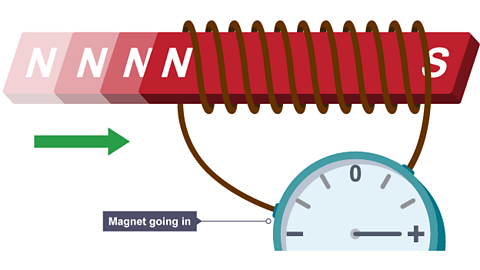
a coil of wire is moved in a magnetic field
a magnet is moved into a coil of wire
This is called The production of a potential difference (voltage) when a conductor, such as a wire, is moved through a magnetic field or exposed to a varying magnetic field. If the conductor is part of an electric circuit, an induced current will flow. and is often referred to as the generator effect.
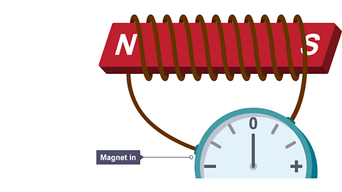
The induced voltage produces an induced current if the conductor is connected in a complete circuit. As with all currents, the induced current creates a magnetic field around itself. Note that this magnetic field opposes the original change. For example, if a magnet is moved into a coil of wire, the induced magnetic field tends to repel the magnet back out of the coil. This effect occurs whether a magnet is moved into a coil, or a coil is moved around a magnet.
Factors affecting the induced potential
The direction of the induced current depends on the direction of movement of the magnet relative to the coil. The current is reversed when:
the magnet is moved out of the coil
the other pole of the magnet is moved into the coil.
The magnitude of the induced potential may also be increased by:
- Increasing the speed of the magnet
- Increasing the strength of the magnet (and the magnetic field)
- Increasing the number of turns on the coil of wire
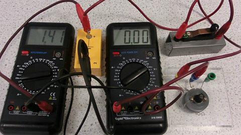
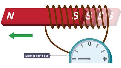
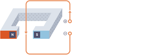
The image below illustrates a simple experiment to demonstrate electromagnetic induction.
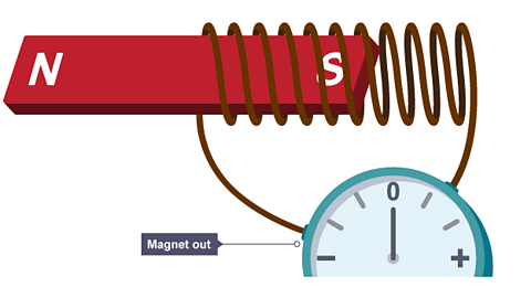
Image caption, A bar magnet rests outside a wire coil connected to an ammeter showing no current
1 of 4
Extended syllabus content: Relative directions of force, field and induced current
If you are studying the Extended syllabus, you will also need to know about the relative directions of force, field and induced current. Click 'show more' for this content:
The force on a given length of wire in a The region around a magnet where a force will be experienced. increases when:
- the current in the wire increases
- the strength of the magnetic field increases
For any given combination of current and magnetic field strength, the force is greatest when the direction of the current is 90В° to the direction of the magnetic field. There is no The effect where a force is exerted on a wire carrying a current in a magnetic field. force if the current and magnetic field are parallel to each other.
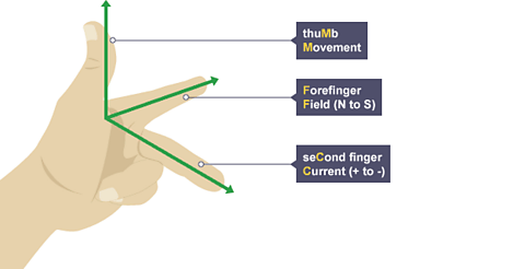
The direction of a motor effect force can be found using Fleming’s left hand rule.
Hold your thumb, forefinger and second finger at right angles to each other:
the forefinger is lined up with magnetic field lines pointing from north to south
the second finger is lined up with the current pointing from positive to negative
the thumb shows the direction of the motor effect force on the conductor carrying the current
In which direction will this wire feel a force?
With forefinger (magnetic field) pointing left to right, and second finger (current) pointing down, your left thumb (force) will point towards you. This is the direction in which the force acts.
Video: Electromagnetism
Jonny Nelson introduces an animated explanation of electromagnetism
The a.c. generator
Extended syllabus content: a.c. generators
If you are studying the Extended syllabus, you will also need to know about a.c. generators. Click 'show more' for this content:
An alternating current (a.c.) Device that converts kinetic energy into electrical energy. is a device that produces an A measure of the electrical work done moving each unit of charge around a circuit..
A simple Alternating current, eg the mains supply of electricity from a plug is alternating current. generator consists of a coil of wire rotating in a magnetic field. Cars use a type of a.c. generator, called an An electrical generator which produces alternating current, an ac generator. to keep the battery charged and to run the electrical system while the engine is working.
The alternator
The diagram shows a simple alternator.
A slip ring is a device used in a motor which allows the transmission of current from a station device to a rotating one. In this instance, the slip rings allow the current to be transmitted from the rotating coil to the external circuit.
As one side of the coil moves up through the magnetic field, a potential difference is induced in one direction. As the rotation continues and that side of the coil moves down, the induced potential difference reverses direction. This means that the alternator produces a current that is constantly changing. This is alternating current (a.c.).
Extended syllabus content: a.c. generators-related graphs
If you are studying the Extended syllabus, you will also need to know about the sketching and interpretation of a.c. generators-related graphs. Click 'show more' for this content:
Alternator output on a graph
The output of an alternator as it rotates can be represented on a potential difference-time graph with potential difference (voltage) on the vertical axis and time on the horizontal axis.
The graph shows an alternating The shape of the graph obtained for y = sin x. The voltage produced by an ac generator follows a sine curve.. The maximum potential difference or current can be increased by:
- increasing the rate of rotation
- increasing the strength of the magnetic field
- increasing the number of turns on the coil
The diagram shows four different positions of the coil in an alternator, and the corresponding potential difference produced.
A - The coil is at 0В°. The coil is moving parallel to the direction of the magnetic field, so no potential difference is induced.
B - The coil is at 90В°. The coil is moving at 90В° to the direction of the magnetic field, so the induced potential difference is at its maximum.
C - The coil is at 180В°. The coil is moving parallel to the direction of the magnetic field, so no potential difference is induced.
D - The coil is at 270В°. The coil is moving at 90В° to the direction of the magnetic field, so the induced potential difference is at its maximum. Here, the induced potential difference travels in the opposite direction to what it did at B.
A - The coil is at 360В°, ie it is back at its starting point, having done a full rotation. The coil is moving parallel to the direction of the magnetic field, so no potential difference is induced.
The magnetic field around a current-carrying wire
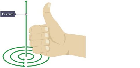
When a current flows in a wire, it creates a circular The region around a magnet where a force will be experienced.around the wire. This magnetic field can To cause something to change direction. the needle of a magnetic compass.
The direction of the current and magnetic field can be found using the right hand grip rule. Coil the fingers of the right hand as if holding the handlebars of a bicycle, with the thumb pointing away from the hand. The thumb indicates the direction of the current, and the fingers then indicate the direction of the magnetic field.
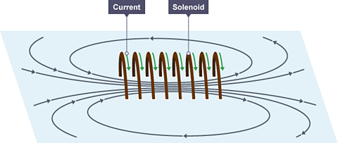
Solenoids
A A straight coil of wire which can carry an electric current to create a magnetic field. consists of a wire coiled up into a spiral shape. When an electric current flows, the solenoid acts as an electromagnet. The shape of the magnetic field is very similar to the field of a bar magnet.
Electromagnets are used in devices such as door locks that can be controlled remotely and electric bells.
Patterns of magnetic fields
Plotting compasses can be used to identify the pattern of magnetic fields in current carrying wires and solenoids.
Plotting compasses can also be used to see the magnetic field around a solenoid.
Iron is a magnetic metal. Instead of using plotting compasses, iron filings can be used instead.
Loudspeakers and headphones
The motor effect is used inside headphones, which contain small loudspeakers. In these devices, variations in an electric current cause variations in the magnetic field produced by an electromagnet. This causes a cone to move, which creates pressure variations in the air and forms sound waves.
Alternating current supplied to the loudspeaker creates sound waves in the following way:
- a current in the coil creates an electromagnetic field
- the electromagnetic field interacts with the permanent magnet generating a force, which pushes the cone outwards
- the current is made to flow in the opposite direction
- the direction of the electromagnetic field reverses
- the force on the cone now pulls it back in
- repeatedly alternating the current direction makes the cone vibrate in and out
- the cone vibrations cause pressure variations in the air, which are sound waves
To make a loudspeaker cone vibrate correctly, the electric current must vary in the same way as the desired sound.
Relays
Relays are electronically operated switches. They consist of two circuits. The first circuit is used to switch on the second one.
The first circuit is a simple electromagnet in series with a battery or cell and a switch. When the switch is turned on current flows and the electromagnet attracts the iron rocker arm to it. The arm pivots and pushes the contacts in the second circuit together. This completes this second circuit so current can flow and the motor is switched on.
Relays can use a low current in circuit one to switch on a much greater current in circuit two. This allows a small current to be used to turn on a powerful motor or bright lights.
Extended syllabus content: Magnetic field direction and strength
If you are studying the Extended syllabus, you will also need to know about magnetic field direction and strength. Click 'show more' for this content:
The strength of the magnetic field around a wire is greatest closest to it.
Fleming's left hand rule shows that changing the direction of the current in a straight wire or a solenoid reverses the direction of the magnetic field.
The strength of the magnetic field around a wire is directly proportional to the current. The strength of the magnetic field in a straight wire can also be increased by winding it into a solenoid. The more coils that a solenoid has the stronger the magnetic field.
The field inside a solenoid is strong and uniform.
Force on a current-carrying conductor
A wire carrying a current creates a magnetic field. This can interact with another magnetic field, causing a force that pushes the wire at right angles. This is called the motor effect.
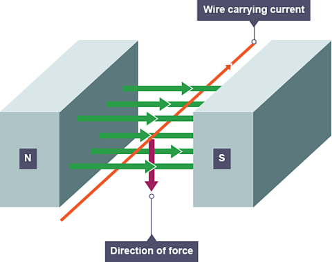
The greatest force is experienced when the wire is at right angles to the magnetic field. The force weakens as the angle moves away from this until there is no force when the wire is parallel with the magnetic field.
When the current is reversed so is the force. When the magnetic field is reversed so is the current.
With the forefinger (magnetic field) pointing left to right, and the second finger (current) pointing down, your left thumb (force) will point towards you. This is the direction in which the force acts.
Extended syllabus content: Relative directions of force, magnetic field and current
If you are studying the Extended syllabus, you will also need to know about the relative directions of force, magnetic field and current. Click 'show more' for this content:
The direction of a motor effect force can be found using Fleming's left hand rule.
Hold your thumb, forefinger and second finger at right angles to each other:
the forefinger is lined up with magnetic field lines pointing from north to south
the second finger is lined up with the current pointing from positive to negative
the thumb shows the direction of the motor effect force on the conductor carrying the current
With your forefinger (magnetic field) pointing left to right, and your second finger (current) pointing down, your left thumb (force) will point towards you. This is the direction in which the force acts.
Extended syllabus content: Particle beams
If you are studying the Extended syllabus, you will also need to know about particle beams. Click 'show more' for this content:
Current is the flow of charged particles. So Fleming's left hand rule can also be used to determine the direction of the force of a particle beam. Conventional current flows from positive to negative.
a beam of positively charged particles will be moving in the same direction as your thumb is pointing
a beam of negatively charged particles will be moving in the opposite direction to your thumb.
The d.c. motor
A coil of wire carrying a current in a magnetic field experiences a force that tends to make it rotate. This effect can be used to make an electric motor.
The turning effect can be increased by increasing the:
- number of coils of wire
- current
- strength of the magnetic field
Extended syllabus content: Operation of an electric motor
If you are studying the Extended syllabus, you will also need to be able to describe the operation of an electric motor. Click 'show more' for this content:
The diagram shows a simple motor using direct current (d.c.).
Starting from the position shown in the diagram of the d.c. motor:
current in the left hand part of the coil causes a downward force and current in the right hand part of the coil causes an upward force
the coil rotates anti-clockwise because of the forces describe above
When the coil is vertical, it moves parallel to the magnetic field, producing no force. This would tend to make the motor come to a stop, but two features allow the coil to continue rotating:
the momentum of the motor carries it round
a split ring commutator changes the current direction every half turn
Once the conducting brushes reconnect with the commutator after a half turn:
current flows in the opposite direction through the wire in the coil
each side of the coil is now near the opposite magnetic pole
Transformers
A An electrical device that increases, or decreases, the potential difference (voltage) of an alternating current. is a device that can change the The potential difference (or voltage) of a supply is a measure of the energy given to the charge carriers in a circuit. Units = volts (V). This is the voltage between two points that makes an electric current flow between them. or The potential difference across a cell, electrical supply or electrical component. It is measured in volts (V). of an alternating current:
- a step-up transformer increases the voltage
- a step-down transformer reduces the voltage
A basic transformer is made from two coils of wire, a primary coil from the alternating current (a.c) input and a secondary coil leading to the a.c output. The coils are not electrically connected. Instead, they are wound around an iron core. This is easily magnetised and can carry The region around a magnet where a force will be experienced. from the primary coil to the secondary coil.
When a transformer is working:
a primary voltage drives an Also called ac. An electric current that regularly changes its direction and size. through the primary coil
the primary coil current produces a magnetic field, which changes as the current changes
the iron core increases the strength of the magnetic field
the changing magnetic field induces a changing potential difference in the secondary coil
the induced potential difference produces an alternating current in the external circuit
Key fact: transformers can only work with alternating current.
The ratio of potential differences on the An electrical device that increases, or decreases, the potential difference (voltage) of an alternating current. coils matches the ratio of the numbers of turns on the coils.
This equation can be used to calculate what the output might be from a particular transformer, or to work out how to design a transformer to make a particular voltage change:
\(\frac{primary~voltage}{secondary~voltage} = \frac{number~of~turns~on~primary~coil}{number~of~turns~on~secondary~coil}\)
\(\frac{V_p}{V_s} = \frac{n_p}{n_s}\)
This is when:
- Vp is the potential difference in the primary (input) coil in volts (V)
- Vs is the potential difference in the secondary (output) coil in volts (V)
- np is the number of turns on the primary coil
- ns is the number of turn on the secondary coil
- In a step-up transformer, Vs>Vp. In a step-down transformer, Vs<Vp.
Example
A mains (230 volt) transformer has 11,500 turns on its primary coil and 600 turns on its secondary coil. Calculate the voltage obtained from the secondary coil.
\(\frac{V_p}{V_s} = \frac{n_p}{n_s}\)
Rearrange to find Vs:
\(V_s = V_p \times \frac{n_s}{n_p}\)
\(V_s = 230 \times \frac{600}{11,500}\)
voltage from secondary coil, \(V_{s} = 12~V\)
The transformer in the example above is a step-down transformer. This is because there are fewer turns on the secondary coil, and there is a smaller voltage on the secondary coil.
The higher the current in a cable, the greater the energy transferred to the surroundings by heating. This means that high currents waste more energy than low currents.
To reduce energy transfers to the environment, step-up transformers can be used to increase the voltage from power stations to thousands of volts, which lowers the current in the transmission cables. Step-down transformers are then used to decrease the voltage from the transmission cables, so it is safer to distribute to homes and businesses.
Extended syllabus content: Equation for 100% efficiency
If you are studying the Extended syllabus, you will also need to know about the equation for 100% efficiency in a transformer. Click 'show more' for this content:
The power in a wire can be calculated by:
\(power = currentВІ\ Г—\ resistance\)
\(P=\ IВІ\ Г—\ R\)
Where:
- power (\(P\)) is measured in watts (\(W\))
- current (\(I\)) is measured in amps (\(A\))
- resistance (\(R\)) is measured in ohms (О©)
Step up transformers increase the voltage in power stations and so reduce the current. By doing this, the resistance is then decreased which reduces power loss from overheating the electrical cables.
Extended syllabus content: Electrical power
If you are studying the Extended syllabus, you will also need to know about electrical power. Click 'show more' for this content:
To calculate electrical The energy transferred each second, measured in watts (W). Power = work done Г· time taken., use the equation:
\(power = potential\ difference\ Г—\ current\)
This is when:
- power (P) is measured in watts (W)
- potential difference (V) is measured in volts (V)
- current (I) is measured in amperes - also referred to as amps (A)
Assuming that a An electrical device that increases, or decreases, the potential difference (voltage) of an alternating current. is 100 per cent efficient, the following equation can be used to calculate the power output from the transformer:
\(potential\ difference\ across\ primary coil\ Г—\ current\ in\ primary\ coil\ =\ \ \ \ \ \ potential\ difference\ across\ secondary\ coil\ Г—\ current\ in\ secondary\ coil\)
\(V_s \times I_s = V_p \times I_p\)
Example
A step-down transformer converts 11,500 V into 230 V. The power output is used to run a 2,000 W kettle. Calculate the current flowing in the primary coil.
\(V_s \times I_s = 2,000~W \) (from \(P = V I\))
\(V_s \times I_s = V_p \times I_p\)
So \(V_p \times I_p = 2,000~W\)
\(I_p = 2,000 \div 11,500\)
input current\( (I_{p}) = 0.174 :A\)
Quiz
Test your knowledge with this quiz on electromagnetic effects.
Teaching resources
Are you a physics teacher looking for more resources? Share these short videos with your students:
The invention of the electricity generator
More on Electricity and magnetism
Find out more by working through a topic
- count6 of 7

- count7 of 7
- count1 of 7

- count2 of 7