Pneumatics looks at the use of compressed air to create a circuit. A pneumatic circuit is made up of an input, process, and output. Pneumatics are used in everyday life for example compressed air is used for airbrushes, dentist drills, lorry breaks and bicycle pumps.
ANIMATION SEQUENCE
Learning outcomes
JOE
Hello and welcome to Tech Bitez. Today we are discussing the high pressured world of p-neumatics.
SANDY
Pneumatics. Please say you haven't been calling that the whole time. The P is silent.It's pronounced pneumatics. I can see I'm going to have to take charge of this one.
JOE
Yeah. Okay. I'll not fight you on that one.Pneumatics.
ANIMATION SEQUENCE
SANDY
Pneumatic systems use the energy stored in compressed air to produce the required effect.By controlling the flow and release of air through pneumatic components, we can achieve complex sequences of motion.Pneumatic components can be arranged in circuits similarly to electronic circuits.Each component has its own specific symbol. These can be used to design and communicate the layout of a pneumatic circuit.Here are some examples of the most common pneumatic components.A single acting cylinder will only extend through pressure from the pump. The built in spring then returns it to its original position.This is the symbol for the exhaust. This is where the pressurised air can escape. This symbol represents the pressure source. Similar to an electronic circuit, this is how you can activate the pneumatic circuit.This is a push button,a plunger, a roller trip, and a lever.This symbol represents a 3/2 valve. It's called a 3/2 valve because it has three ports on each of its two positions. These can be used to control the pneumatic flow. Any of the activators can be attached to the 3/2 valve to act as the input.
JOE
I think I'm getting the hang of these. Are there any other ways to control their flow?
SANDY
There are indeed. A uni-directional flow regulator, which is this symbol, can be used to incorporate speed control into a system.Another type of control that can be added is a shuttle valve. Which looks like this. A shuttle valve will ensure that the compressed air is only able to flow in one direction. This would be important if there are different inputs.This example shows a simple system that includes a shuttle valve. As you can see, there are two inputs that could activate the single acting cylinder. By adding the shuttle valve, we can ensure that only one source can control the system at any one time.This is known as an OR circuit. Only one or the other of the inputs can activate the system.This circuit is an example of an AND circuit. As you can see, we again have two inputs in this circuit. However, in this case, input one and input two must be engaged to activate the circuit. This is how It gets the name an AND circuit.
JOE
Well, there you have it. Everything you need to know about pneumatics.
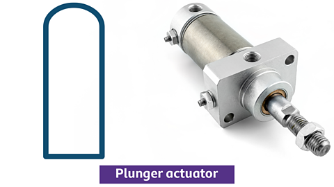
Actuators
An actuator acts like a switch in a pneumatic circuit ÔÇô it allows you to turn the circuit on and off. Valves can be actuated using different methods.
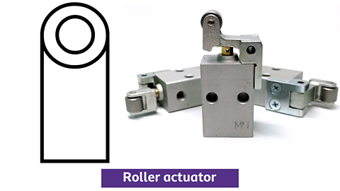
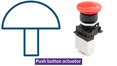
Types of actuator
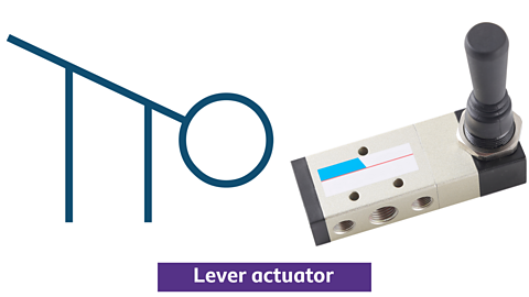
1 of 4
The methods of operation shown above are used to cause a device to operate a 3/2 valve. This means they can be used to turn a circuit on or off.
3/2 valves
3/2 valves are the component used to control a single acting cylinder or piston. A 3/2 valve has three ports and has two states, either on or off which is how it got its name.
A 3/2 valve
- Port 1 ÔÇô This is where the main air supply connects.
- Port 2 ÔÇô Used to connect to the next component in the circuit.
E.g. Connecting to a single acting cylinder (Piston) - Port 3 ÔÇô Where the exhausted air escapes.
Symbols are used to represent the air supply (pressure source) and the exhaust in a circuit.
Exhaust and pressure symbols in a pneumatic circuit
Single acting cylinder
Single acting cylinders have two features which makes them easy to identify ÔÇô they will only ever have one inlet port and they will always have a spring return.
Single acting cylinder
The piston is forced out when air is pushed through the inlet port. When the pressure source is removed the spring will drive the piston back into the cylinder.
Logic circuits
Logic circuits are made through joining valves together. The simplest type of logic circuit is an AND circuit.
AND circuits
Only when both valves A AND B are pressed will the single acting cylinder go positive.

One use for an AND logic of 2 valves is in situations where safety is important. For example, you canÔÇÖt turn a saw on until you have pressed both buttons ÔÇô this means you canÔÇÖt accidentally turn it on.
OR circuits
The two 3/2 valves are connected in parallel. This means that either valve X OR Y can be pressed to make the piston go positive.

This type of circuit is used to allow a machine to be turned off from different positions. This can also be a safety feature as other people can turn the machine off in an emergency
OR circuits will always contain a shuttle valve. A shuttle valve allows air to be routed from either valve X or valve Y depending on which one has been actuated.
Test yourself
More on Control systems
Find out more by working through a topic
- count5 of 5
- count1 of 5
- count3 of 5