Mechanical devices can change one form of force to another. All moving parts work on some sort of mechanism. Mechanical systems all involve an input, process and produce an output.
JOE
Hey there and welcome back to Tech Bitez. Today, we're talking about mechanical control systems.
SANDY
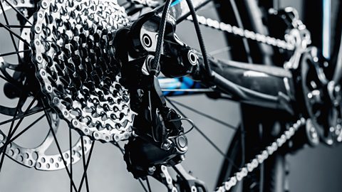
Unlike electrical control systems, a mechanical control system is made up of moving parts. However, the simple flow chart of input process and output are still used to visualise how the system performs. With mechanical control systems, the input is supplied by movement. This is known as the input motion. The output also supplies a motion. This is known as a force. A good example of a mechanical system is a bicycle. The input motion is the force of the cycle feet pushing down on the pedals, which in turn causes the chain to move. The process in this example is the chain revolving, which in turn moves the gears. This converts one type of motion into another. The output is the wheels turning, which causes the bike to move.
There are four different types of motion. There is rotary motion. Rotary motion moves in a complete cycle. For example, our bike wheel. There is linear motion. Linear motion moves in a straight line in one direction. For example, a train and travelling down a track. There is oscillating motion. Oscillating motion moves in a repetitive to and fro motion, for example, the pendulum in a mechanical clock. Lastly, there is also reciprocating motion. Reciprocating motion moves backwards and forwards along a straight line. For example, a piston in an engine. The best mechanical control systems are actually very efficient in terms of the effort inputs versus the output. Often using mechanical advantage to ensure that the force output from the system is greater than the input motion. Pulleys and levers are good examples of this. Pulleys and levers are both simple mechanical control systems that can be used to move large objects. A simple single pulley system changes the direction of the force applied without adding a mechanical advantage. For example, pulling down in the rope is simpler than lifting the object. Having no mechanical advantage means that the motion that is input will be the same as the force output. By adding another pulley to the system, we can achieve a mechanical advantage. In this two-pulley system, the effort required to lift the object will be halved. Adding more pulleys to the system will increase mechanical advantage. This means the force output will be much greater than the movement input. I'll just pretend that I haven't already gone through all this with you before. Levers like pulleys use mechanical advantage to make moving a load more efficient. Levers are made up of three main parts. Effort, this is the amount of force supplied by the user. Fulcrum, this is the point the lever pivots around. Load, this is the weight that needs to be moved. Levers are divided into three different classes. These are all defined by the order in which the effort, fulcrum, and load, are placed. First class Levers. These place the fulcrum between the load and the effort. An example of this is a pair of scissors. Second class levers. These place the fulcrum at one end of the lever and the effort of the other. The load is placed in the middle. An example of this is a wheelbarrow. Third class levers. These place the effort between the fulcrum and the load. An example of this is a pair of tweezers.
JOE
Well, there you have it. Mechanical control systems and what they're all about. Wouldn't mind adding some mechanical advantages into my life. Think I could get a class of levers to help tidy my room?
SANDY
That better be a joke.
Types of motion
Mechanical devices all have an input motion, which transforms into force to make an output motion.
The four types of motion are:
- linear
- rotary
- reciprocating
- oscillating
Examples of motion types

╠²
Movement in a straight line.


╠²
Motion that moves around an axis or pivot point.


╠²
Repeated movement up and down or back and forth


╠²
Curved movement backwards and forwards ÔÇô movement that swings.

Levers
Levers have three main parts:
- Effort - the amount of force applied by the user, also referred to as the input
- Fulcrum - where the lever pivots
- Load - the weight that needs to be moved, also referred to as the output
There are three different types of levers. They are chosen for their ability to produce the most mechanical advantage for a particular task. The effort, fulcrum and load are arranged in different orders, the class of lever depends on which section of the lever is in the middle.
Class 1 lever
A class 1 lever has the Fulcrum in the middle. E.g., Using a crowbar.
Class 2 lever
A class 2 lever has the Load in the middle. E.g., A wheelbarrow.
Class 2 lever
Class 3 lever
A class 3 lever has the Effort in the middle. E.g., Using tongs
Mechanical advantage is the amount of help you get using a machine in comparison to doing something with just human effort, and it is created by levers.
Cams and followers
- a cam - attached to a , which rotates
- a follower - touches the cam and follows the shape, moving up and down
Cams
Cams come in a variety of different shapes. Each shape leads to the follower producing a different outcome and are therefore used for different applications.
There are four main shapes of cams. Depending on the use and the desired output movement different shapes can be used.
Pear cam
Circular cam
Heart shaped cam
Drop cam
Followers
Followers also come in a variety of different shapes the three main types are flat, knife and roller.
Flat follower
Point or knife follower
Roller follower
Pulley and belt systems
Pulleys
Pulleys use
One pulley doesnÔÇÖt make a mechanical advantage, as the same amount of force is needed. However, if additional pulleys are added, a mechanical advantage is created. Using two pulleys together means you need half the force to lift.
Belt drives transfer movement from one rotating pulley to another, each held on a A circular rod that mechanical parts such as pulleys sit on. Shafts and pulley wheels can be made out of any material, whereas pulley belts are generally made from a soft, flexible material such as rubber. Grooves on the pulleys and belts help them to grip and turn.

Belts
Belts can be attached around different-sized pulleys to drive shafts to change speed. As with gears, the bigger the wheel, the slower the speed. The Distance moved by effort over the distance moved by load. between two pulleys can be calculated.
Velocity ratio = diameter of the driven pulley ├À diameter of the driver pulley
This can then be used to calculate the output speed.
Output speed = input speed ├À velocity ratio
Example
A driven pulley has a diameter of 120 mm and a driver pulley has a diameter of 40 mm.
Velocity ratio = diameter of the driven pulley ├À diameter of the driver pulley
= 120 ├À 40 = 3 or 3:1
The smaller driver pulley turns three times to make the driven pulley turn once.
The output speed of the larger driven pulley can then be calculated using the information available - the input speed is 100 revolutions per minute (rpm) and the velocity ratio has been calculated as 3.
Output speed = input speed ├À velocity ratio
= 100 ├À 3 = 33 rpm
Gears
Gears are wheels with teeth around the outside, the simplest form of which is a A gear with teeth that project outwards from a cylinder.. When several wheels are interlocked, they can transfer motion from one place to another, eg in some hand whisks or on bikes.
Gear trains are when two or more gears are joined together. In a simple gear train, the The starting gear in a gear train that causes all other movement. causes the Transfers motion from the drive gear. to turn in the opposite direction.
Smaller gears with fewer teeth turn faster than larger gears with more teeth. This difference in speed is called the gear ratio.
Example
The driven gear has 60 teeth and the drive gear has 15 teeth.
Gear ratio = 60 ├À 15
= 4
For each rotation of the drive gear, the driven gear would rotate four times.
Gear ratio = 4:1
This is known as gearing up. If the driven gear had 15 teeth and the drive gear had 60 teeth, the gear ratio would be 4:1 which is known as gearing down.
Large gear moving a small gear = Gearing up
Small gear moving a large gear = Gearing down
If the drive gear and the driven gear are separated by another gear, called the idler, they will move in the same direction.
Test yourself
More on Control systems
Find out more by working through a topic
- count4 of 5
- count5 of 5
- count1 of 5